Detailed Description

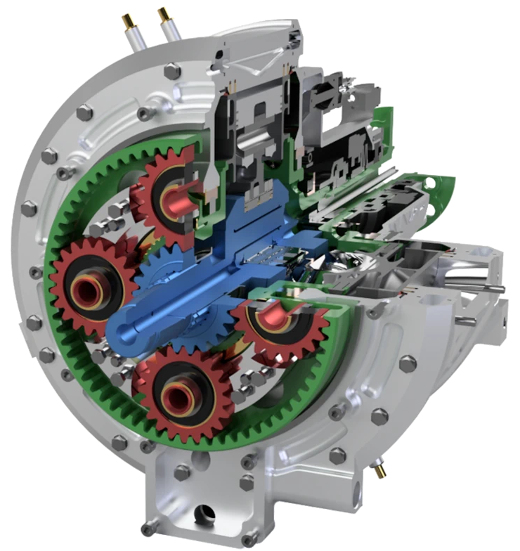
The birotary engine conception is a three-cylinder spark ignition piston engine. The engine’s three cylinders are arranged in a “star” at 120° angles and move within a rotating cylinder block. Its cylinder block rotates in a stationary case, in which the intake, exhaust ports and spark plugs are placed. The case is also the cylinder head and has two combustion portions. Each combustion portion is equipped with its own intake and exhaust port, and set of spark plugs. The rotating cylinder block also fulfils the function of slide valvetrain and provides the charge exchange in the cylinders. The cylinder block rotates in opposite direction to the crankshaft. The crankshaft and cylinder block are connected by means of planetary gear set with gear ratio of three (i.e., the crankshaft revolves three times per each cylinder block rotation). This means that for example at 8000 RPM of the engine, the cylinder block rotates at 2000 RPM in one direction and while the crankshaft rotates at 6000 RPM in the opposite direction. The engine completes a four-stroke work cycle once every 720° of relative angle, which means 180° of cylinder block angle plus 540° of crankshaft angle. Each cylinder makes four strokes for every 180° of cylinder block movement, i.e., two full working cycles per block rotation. Figure below shows the engine action trough one four-stroke work cycle.

Patented Combustion Chamber Sealing
Combustion chamber sealing is a critical element of all rotary engines. Our combustion chamber sealing solution is the most important contribution and innovation of the KNOB Birotary engine concept. Our innovative solution has been patented as a stand-alone invention. In USA, a combined patent comprising cylinder, engine and layout was also granted.
Seal Assembly
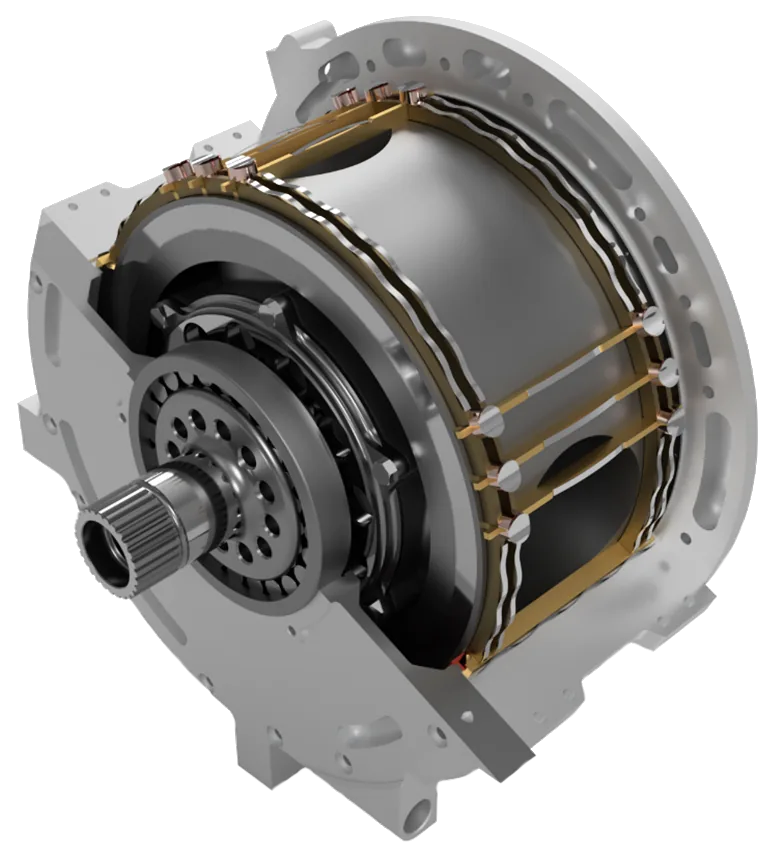
The seal assembly comprises of a side seal, transverse sealing strips, joints and springs. The side seal is divided into circular segments always placed between neighboring transverse sealing strips. The transverse sealing strips pass through the side sealing segments notably reaching over the cylinder bore. This solution prevents excessive bending of sealing strips into the cylinder. Joints are located between the side sealing segments and transverse sealing strips. Each sealing element, including its joints, is equipped with its own spring, which presses it towards the cylinder block. Joints also press the elements, which they sit on.

Placement of sealing elements in the stationary case ensures the stable application of force on the sealing elements and this force is unrelated to engine speed, unlike the Wankel rotary engine. This feature facilitates a very high engine speed and high specific output parameters. All the transverse sealing strips and side sealing segments have a surface or tangential contact with the outer, rotational surface of the cylinder block, which decreases contact stresses of the sealing elements and the outer surface of the cylinder block. This surface contact of the seal also requires less seal lubrication and increases its efficiency and durability. The sealing of the high-pressure portion in the cylinder, i.e. between the cylinder block and stationary case, is multiple in both, axial and tangential directions. It ensures high reliability of this Seal assembly of engine in the connection with the cylinder block solution. The side sealing segments are placed on the edge of the cylinder bore thus minimizing the crevice between the cylinder block and stationary case.