The purpose of this page is to use computer simulations to approach the issue of internal combustion engine vibrations caused by the combustion cycle. Those Vibration Simulations are performed in different engine configurations and operating modes. From the simulations, we can see what effect has on the resulting vibrations appropriate motor arrangement.
Introduction
The simulations were carried out on simplified engine models, but in such a way as to preserve the important parameters that have the greatest influence on the production of vibrations. The main components in the simulations are based on the real parts used in the functional sample. It is clear from the videos that individual parts such as heads, cylinders, connecting rods and pistons are identical in all simulations and have the same dimensions and weight as the real parts. Generator rotors are of two sizes. In most cases, only one larger generator is used. In the case where two smaller generators are used, each generators have half the power.
Of course, there are differences between the individual simulations, for example in the specific balancing of the crankshaft in the Range Extender. All parts that have almost no effect on engine balance and vibration are either simplified or omitted (for example generators stator) to make the simulated issue easier to see.
The important differences are described in more detail in each simulation. The entire 3D model is then placed on a solid stand. The stand is connected to the engine crankcase at four points by means of flexible joints. Coiled springs are used in the simulations so that the degrees of freedom are preserved, and the model can move according to the resulting forces. All springs and their damping effects (resistance) and other parameters are identical in all simulations.
Finally, boundary conditions were applied to the model. The braking torque of the generator and the variable pressure force acting on the piston to simulate the actual behavior of the engine.
Basic model parameters:
- Bore and stroke: 58.0 x 57.9 mm
- Simulated revolutions: 2000-2500 rpm
Boundary conditions:
The braking torque of the generator has a constant magnitude and simulates the power draw from the generator. For the larger generator, the torque is around 38 Nm, and for the smaller generator, the torque is around 19 Nm.
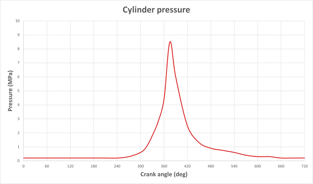
The pressure force acting on the piston and cylinder head is defined by the pressure in the cylinder which is shown on the Cylinder pressure graph.
In the case of simulations with a misfire condition on one cylinder, the generator torque is reduced.
The braking torque of the generator is zero in the simulations where there are no pressure forces on the piston resulting in the pistons generating no power.
Boxer Engine
For simplicity in this simulation where we are using a two-cylinder boxer engine, we did not use balance shafts to compensate the moment from the inertial forces of the sliding masses, in the plane passing through both cylinder axes. The influence of this moment on the generation of vibrations is very small compared to the influence of the combustion cycle.
In the first video below of the engine generator simulation ‘Boxer Engine – without ignition’, the engine is shown running without compression and combustion pressures in the cylinders. It is important to note that the engine is deliberately modeled with a large axial distance between the cylinders to make it more visible the immediate effect this shift has on the produce of vibrations. it can be seen that the engine is well balanced and has only minimal oscillations, even in the case of such an inappropriate design.
The second video demonstrates the simulation of the engine generator ‘Boxer Engine – with ignition’, operating with compression and combustion pressure in the cylinders that matches the above-mentioned Cylinder pressure graph. It is clearly visible how the engine oscillates in the rhythm of the ignition in the cylinders. The pressure force on the piston is shown by the red vector, so it is clear that the dominant vibration is caused by the combustion process in the engine cylinders. This is, after all, is the problem of every motor-generator arrangement, (where the rotor of the generator is located directly on the crankshaft) and standard design for internal combustion engines.
Parallel Twin Engine
In the simulation of a motor-generator using a Parallel Twin engine, the duty cycle shift between the cylinders is 360 degrees. In this model, one balancer shaft is used to balance the first harmonic component of the sliding forces. Balancing was carried out according to the standard procedure. In this model, it would be possible to use two or four balancing shafts for better compensation of the 1st and possibly also the 2nd harmonic components of the inertial forces. A larger number of balancing shafts does not have a significant cumulative effect on the resulting vibrations, which are mainly caused by the combustion process. In practice, the solution with one balance shaft is the most common.
The ‘Parallel Twin Engine’ motor-generator simulation video demonstrates, operation with compression and combustion pressures in the cylinders that match the Cylinder pressure graph above. Similar to the previous version with a Boxer engine, you can see how the engine oscillates in the rhythm of the ignition in the cylinders. The pressure forces on the piston are also shown by the red vectors.
Range Extender
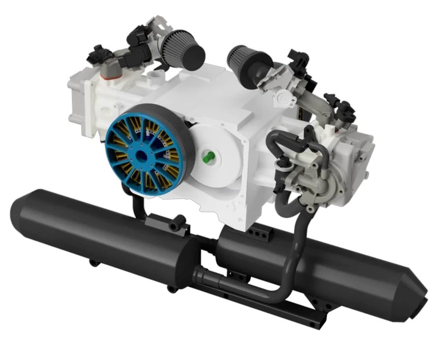
In the upcoming section, we showcase simulations of our patented motor-generator solution in various setups, and accompanied of some examples of different types of fault conditions.
Range Extender with a flywheel
As a starting point, we used the Range Extender version with one generator and a flywheel. This design is the closest to the previous models and uses the same generator.
In the following two simulation videos we show the range extender simulation without compression and combustion pressure in the cylinders, as well as a variant of the simulation where the engine operates with compression and combustion pressures in the cylinders. It’s similar to the previous simulations of the Boxer motor-generator. The pressure force on the piston is also shown by the red vectors. In both videos, it is worth noting that there are no oscillations of the motor-generator, even when compressive forces are applied. This simulation demonstrates how vibration are reduced to zero. Perfect elimination of vibrations is achieved thanks to the symmetrical location of the crank mechanisms, their balance and mutual synchronization. At the same time, it is necessary to maintain the same magnitude of the moment of inertia of both crank assemblies.
The gears in this version of the range extender transfer part of the power from the shaft with the flywheel to the shaft with the generator. However, the transmitted torque is relatively small, proportional to the effective transmitted power. The peak magnitudes of the moment, caused by the ignition in the cylinders, are absorbed by the acceleration of the flywheel and the corresponding acceleration of the generator rotor.
Range Extender with two generators
The Range extender with dual generators distinguishes itself from the earlier version by replacing the large generator and flywheel with two smaller generators.
In the following two simulation videos of this version of the range extender, the simulation shows the engine operation without and with compression and combustion pressures in the cylinder. The videos are similar to the previous simulation with one generator and a flywheel. These videos also confirm the preposed perfect elimination of vibrations.
Compared to the previous version of the range extender, this version has a more favorable load on the synchronization gears. Their load is close to zero, and therefore the mechanical losses in the transmission are also negligible. At the same time, it is also the most advantageous solution in terms of the total weight of the equipment because the flywheel is eliminated.
Simulation of failure operation of the Range Extender
(misfire on one cylinder)
The next simulations relate to the aforementioned variants of our motor-generator in a fault condition.
In the following two videos of simulations, the operation of the motor-generator in the event of a failure of compression and ignition on one cylinder is shown. The compression force is applied only on one cylinder and again the force is shown by the red vector.
In both videos, it is obvious that there are no oscillations of the motor-generator. These simulations demonstrate the reduction of vibrations to zero even in with the fault condition of the engine.
An ignition failure does not affect the balance of the inertial forces. Due to the synchronization of crankshafts rotation, the angular accelerations of those shafts are the same. Thanks to the identical moment of inertia on both crank assemblies, all moments arising from the action of angular accelerations are completely compensated.
The synchronizing gears will be significantly more loaded when the range extender malfunctions. It must transmit the torque required to accelerate the crankshaft at the cylinder where the ignition failure occurred.
Simulation of failure operation of the Range Extender
(breaking the rule of the same moment of inertia on both crank assemblies)
The configuration of this range extender does not match with our patented design. Its inclusion here is deliberate, as it demonstrates the core principles behind our zero-vibration solution more clearly.
The simulation is identical to the range extender variant mentioned above with one generator and a flywheel, the key difference being that the flywheel is removed. This disrupts the state where the same moment of inertia is exerted on both crank assemblies.
In the first video of the motor-generator simulation with one generator and without a flywheel, you can see, the engine running without compression and combustion pressures in the cylinders. Thanks to the symmetry and synchronization of the movement of the crankshafts, all inertial forces are completely compensated. In this video it is clearly visible that the oscillations are very small.
In the second video you can see, the simulation with compression and combustion pressures in the cylinders according to the above mentioned Cylinder pressure graph. It is clearly visible that the engine oscillates in rhythm with the ignition in the cylinders. The pressure force on the piston is shown by the red vectors again. So it is obvious that the dominant vibrations are caused by the combustion process in the engine cylinders. This is a result of the different moment of inertia between the crankshaft with the generator and the other crankshaft.
Comparison of different variant of motor-generators
The following video is a compilation of the previous simulation videos, so you can see the differences between the different type of motor-generators and their vibrations in the standard operation mode.
Conclusion
From the above simulations, it is clear that the motor-generator according to our patented solution has vibrations that approach zero. In a real world design, it is necessary to take into account the same size and mass of the sliding parts and the same value for the moment of inertia on both crank mechanism assemblies. It is also necessary to balance the rotating masses as best as possible. The design must also have a sufficiently rigid connection between the crank and the generator as well as the flywheel in order to avoid torsional resonances.
From the simulations of motor generators with classic engines with one crankshaft, it is obvious that the ignitions in the cylinders have the greatest influence on the vibrations.
It is known that in single crankshaft motor-generators, vibrations caused by angular accelerations can be compensated by using a gear transmission that reverses the rotation of the generator against the crankshaft assembly rotation. But, this transmission must be very rigid and sufficiently dimensioned to withstand large instantaneous torques during ignition in the cylinders. However this is less advantageous in terms of the weight of the solution, mechanical losses and other properties when compared to how this problem is ideally solved in our design of the motor-generator.